Маркировка: 4 кольца 5 колец 6 колец
Сопротивление, допуск: 4444Ом ± 10%
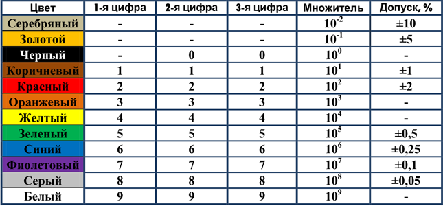
| 1е значение | 2е значение | 3е значение | 4е значение | Множитель | Допуск | |
| Серебряный | — | — | 0.01 | ± 10% | ||
| Золотой | — | — | 0.1 | ± 5% | ||
| Черный | 0 | 0 | 0 | 0 | x1 | — |
| Коричневый | 1 | 1 | 1 | 1 | x10 | ± 1% |
| Красный | 2 | 2 | 2 | x100 | ± 2% | |
| Оранжевый | 3 | 3 | 3 | 3 | x1K | — |
| Желтый | 4 | 4 | 4 | 4 | x10K | — |
| Зеленый | 5 | 5 | 5 | 5 | x100K | ± 0.5% |
| Голубой | 6 | 6 | 6 | 6 | x1M | ± 0.25% |
| Фиолетовый | 7 | 7 | 7 | x10M | ± 0.05% | |
| Серый | 8 | 8 | 8 | 8 | x100M | ± 0.05% |
| Белый | 9 | 9 | 9 | 9 | x1Г | — |
|
Резисторы – это элементы для построения электрических схем, предназначенные для контроля и регулирования величины силы тока. Разделяют на постоянные, переменные, подстроечные. Для идентификации постоянных резисторов SMD – устройств, монтируемых на поверхность, – все производители разработали буквенно-цифровые обозначения для крупных элементов и цветовой код для деталей очень маленьких размеров. Онлайн-калькулятор дает возможность удобно и быстро узнать номинал по цветам колец. Программа рассчитана на распознавание изделий с маркировкой, состоящей из четырех или пяти колец. Способы определения сопротивления резистораПри отсутствии буквенно-цифровой маркировки можно воспользоваться одним из следующих способов:
Как определить номинал резистора по цветовой маркировке с помощью онлайн-программы?Детали малой мощности имеют очень маленькие размеры (длина – несколько миллиметров, диаметр – около миллиметра), поэтому наносить буквенно-цифровую маркировку сложно. Для таких изделий используют цветные точки и линии, характеризующие основные параметры. Преимущества цветовой схемы:
Количество цветных полос зависит от точности, которую обеспечивает деталь:
Принцип работы с онлайн-сервисом
Идентификация резистора по универсальной таблицеВ зависимости от количества полос, цветной код с использованием сводной таблицы расшифровывается следующим образом:
Эти правила маркировки актуальны для непроволочных деталей с гибкими выводами. Различия в обозначении проволочных вариантов: первая широкая полоска означает не сопротивление, а технологию изготовления, последнее цветное кольцо может характеризовать особые свойства детали, например устойчивость к огню. Была ли статья полезна?Да Нет Оцените статью Что вам не понравилось? Другие материалы по теме Специалист в области радиоэлектроники и электронных компонентов. Консультант по подбору деталей в компании РадиоЭлемент. |
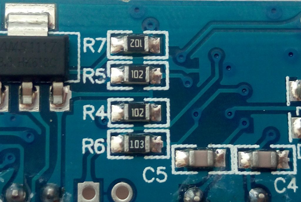
Как правило, в большинстве случаев цветовая маркировка резисторов предназначается для малогабаритных резисторов, на которых практически невозможно нанести обычное цифровое обозначение. Одним из преимуществ цветовой маркировки резисторов является то, что достаточно легко определить номинал резистора, который расположен на печатной плате.
Определение величины сопротивления постоянного резистора по цветовым кольцам не является нечто сложным. Достаточно знать соответствие цвета полоски конкретной цифре и далее по определенной методике вычислить сопротивление резистора.
Как правило, маркировочные полосы сдвинуты в одну сторону, и чтение их выполняют слева направо. В случае если размер резистора мал и кольца заполняют равномерно всю поверхность резистора, то первую полосу делают несколько шире, чем все остальные.
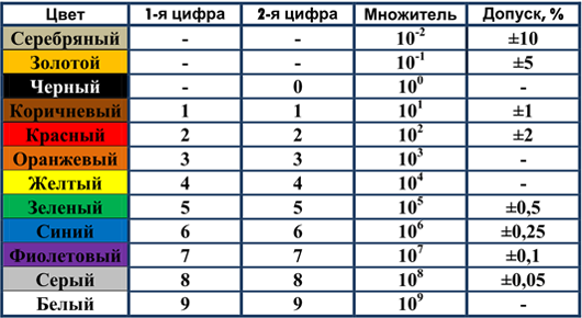
И так сначала приведем таблицу соответствия:
Определение сопротивления резистора с 4 цветовыми кольцами
Четыре цветных кольца – наиболее распространенная маркировка. Первые две полосы формируют двухзначное число сопротивления, третья полоса определяет множитель. Четвертая полоса сообщает о допустимом отклонении сопротивления в большую или меньшую сторону от номинала.
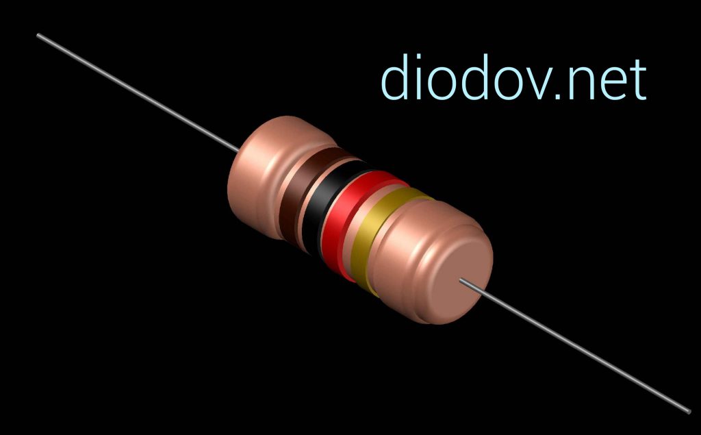
Рассмотрим на примере (по рисунку «А»)
Имеем резистор с цветными полосками: красный, черный, коричневый, золотистый.
- Красный – 2
- Черный – 0
- Коричневый – 10
- Золотистый – 5%
Результат: 20 х 10 = 200 Ом с отклонением 5%.
Определение сопротивления резистора с 5 цветовыми кольцами
Постоянные резисторы с пятью цветными полосками тоже не редкость. Определение сопротивления аналогично, как и с четырьмя полосами. Первые три полоски определяют трехзначное число сопротивления, а четвертая является общим множителем. Пятая полоса в этом случае служит обозначением отклонения в значении сопротивления.
Рассмотрим на примере (по рисунку «В»)
На резисторе есть полосы: красный, желтый, черный, оранжевый, золотистый
- Красный – 2
- Желтый – 4
- Черный – 0
- оранжевый – 1000 (1к)
- Золотистый – 5%
Результат: 240 х 1000 (1к) = 240 кОм с отклонением 5 %.
Цветовая маркировка резисторов — онлайн калькулятор
1. Перевода из цифровой кодовой маркировки в значение сопротивления резистора.
2. Перевод значения сопротивления резистора в цифровую кодовую маркировку.

В связи с малыми размерами все типоразмеры SMD-резисторов, кроме резисторов типоразмера 0402 маркируются при помощи цифро-буквенной маркировки.
Правила маркировки SMD-резисторов зависят от допуска и типоразмера.
Резисторы всех типоразмеров с допуском 10%, 5% и 2% маркируются 3-мя цифрами, две первые из них обозначают мантиссу, а третья — показатель степени по основанию 10. Результирующее значение сопротивления получается в Омах.
Пример 3-х цифровой маркировки резистора: 473 имеет сопротивление 47*103 Ом = 47 Ком.
При маркировке малых сопротивлений для обозначения десятичной точки к значащим цифрам добавляется буква R. Например резистор с маркировкой 47R имеет сопротивление 47 Ом.
Четырьмя цифрами маркируются 1% SMD-резисторы типоразмеров от 0805 и выше. Первые 3 цифры обозначают мантиссу, а четвёртая — показатель степени по основанию 10.
Пример 4-цифровой маркировки: 5102 имеет номинал 510*102 Ом = 51Ком.
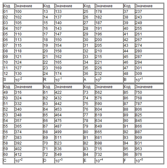
Резисторы типоразмера 0603 с допуском 1% маркируются с использованием таблицы EIA-96 (приведена ниже) двумя цифрами и одной буквой. Цифры обозначают код, по которому из таблицы определяют мантиссу, а буква — показатель степени по основанию 10. Например, маркировка 12D означает, что резистор имеет номинал 130×103 Ом = 130 КОм.
 Обсудить калькулятор сопротивления SMD-резисторов на Форуме
на Ваш сайт.
Статьи
«ЧИП и ДИП» — авторизованный партнер ARROW Central Europe
ARROW Central Europe – глобальный поставщик продуктов, услуг и решений в области электронных компонентов и компьютерных технологий. «ЧИП и ДИП» — авторизованный партнер ARROW Central Europe. Обратившись в «ЧИП и ДИП», Вы можете получить оперативный доступ ко всему комплексу услуг ARROW.
Источники питания Mean Well
Mean Well является одним из ведущих и крупнейших тайваньских производителей источников питания. Продукция компании характеризуется высоким качеством, конкурентоспособными ценами и широтой номенклатуры.
Калькулятор цветовой маркировки резисторов
Калькулятор позволяет рассчитывать сопротивление и допуск сопротивления резисторов с цветовой маркировкой в виде 4 или 5 цветных колец.
Компенсация реактивной мощности / Коррекция коэффициента мощности
В связи с увеличением потребления электроэнергии все более острой становится проблема ее экономии. Повышение качества электроэнергии путем оптимизации коэффициента мощности позволяет уменьшить расходы и ускорить отдачу от инвестиций.
Контакт им не нужен!
«ЧИП и ДИП» предлагает индуктивные и емкостные выключатели хорошо зарекомендовавшего себя на отечественном рынке производителя «МЕГА-К». Датчики разработаны с учетом специфики отечественного производства. Превосходное качество и высокая надежность подтверждены сертификатом ISO 9001:2000
Корпус DIP. Чертежи корпусов импортных микросхем.
Чертежи корпусов DIP8, DIP14, DIP16, CDIP16, DIP18, CDIP18, DIP20, CDIP20, DIP22, DIP24, DIP28, DIP32, DIP36, DIP40, DIP42, DIP48, DIP52, DIP64
Корпус LCC. Чертежи корпусов импортных микросхем.
Чертежи корпусов LCC16, LCC32, LCC36, LCC44, LCC48, LCC64
Корпус PLCC. Чертежи корпусов импортных микросхем.
Чертежи корпусов PLCC18, PLCC20, PLCC22, PLCC28, PLCC32, PLCC44, PLCC68, PLCC84
Корпус SIP. Чертежи корпусов импортных микросхем.
Чертежи корпусов SIP7, SIP8, SIP9, SIP12
Корпус SOIC. Чертежи корпусов импортных микросхем.
Чертежи корпусов SO8, SO14, SO24, SO28, SOP8, SOP14, SOP16, CSOP18, SOP20, SOP24, SOP28, SOP30, SOP32, SOP38, SOP44, SOP64
Корпус SSOP. Чертежи корпусов импортных микросхем.
Чертежи корпусов SSOP8, SSOP16, SSOP20, SSOP24, SSOP30, SSOP34, SSOP40
Корпус TSOP. Чертежи корпусов импортных микросхем.
Чертежи корпусов TSOP24, TSOP26, TSOP28, TSOP32, TSOP40, TSOP44, TSOP48, TSOP50, TSOP54, TSOP86
Корпус ZIP. Чертежи корпусов импортных микросхем.
Чертежи корпусов ZIP12, ZIP16, ZIP17, ZIP19, ZIP20, ZIP24, ZIP40
Корпуса QFP, LQFP, TQFP. Чертежи корпусов импортных микросхем.
Чертежи корпусов QFP28, QFP32, QFP44, QFP48, QFP64, QFP68, QFP80, QFP100, QFP120, QFP124, QFP144, QFP160, QFP164, QFP176, QFP196, QFP208, TQFP64, TQFP80, TQFP100, TQFP120, TQFP168, LQFP32, LQFP48, LQFP64, LQFP80, LQFP100, LQFP120, LQFP144
Министанки Xendoll
Безопасные, точные, компактные электрические министанки XENDOLL — идеальный инструмент для хобби, моделистов, а также для обучения детей в школах, кружках и дома.
Набор программно-аппаратных средств CodeMaster-ARM
CodeMaster-ARM — набор программно-аппаратных средств, предназначенный для разработки и отладки систем на базе микроконтроллеров ARM7/ARM9.
Настройки различных браузеров
Сайт доступен для просмотра в браузерах Internet Explorer 8.0+, Mozilla Firefox 3.5+, Opera 11+, Google Chrome. Все возможности клиентской части доступны при установке в браузере настроек безопасности и конфиденциальности «по умолчанию» (default).
Свинцово-кислотные аккумуляторы DELTA
Свинцово-кислотные аккумуляторы Delta серии DT специально разработаны для нетребовательных систем и оптимизированы для работы в буферном режиме. Аккумуляторы Delta DT имеют низкое внутреннее сопротивление и высокую плотность энергии. Отвечая международным стандартам безопасности, рекомендованы для применения в охранно-пожарных системах и системах контроля и управления доступом.
Сервис «Информация о состоянии счета»
Если вы выписали счет в одном из оптовых отделов «ЧИП и ДИП», при помощи этого сервиса вы можете узнать актуальную информацию о состоянии своего счета: отслеживать прохождение оплаты и отгрузки по счету, смотреть комплектацию товара, видеть контактную информацию по менеджеру, ответственному за обслуживание счета.
Счет на оплату — в режиме online !
Для вашего удобства мы представляем новый сервис – получение счета на оплату Интернет-заказа в режиме online. Теперь в любой момент вы можете зайти в свой «Личный кабинет» на нашем сайте и в разделе «Мои заказы» открыть выставленный к оплате счет, сохранить его у себя или распечатать на принтере.
Типы корпусов импортных диодов
Корпус — это часть конструкции полупроводникового прибора, предназначенная для защиты от внешних воздействий и для соединения с внешними электрическими цепями посредством выводов. Корпуса стандартизованы для упрощения технологического процесса изготовления изделий. Число стандартных корпусов исчисляется сотнями! Ниже представлены наиболее распространенные серии корпусов импортных диодов.
Типы корпусов импортных микросхем
Представлены наиболее распространенные серии корпусов импортных микросхем DIP, SIP, LCC, TSOP, ZIP, SOIC, QFP, PLCC, SSOP
Типы корпусов импортных транзисторов и тиристоров
Представлены наиболее распространенные серии корпусов импортных транзисторов и тиристоров: ADD-A-PAK, DIP4, ITO-220, MT-200, S6D, SC72, SC95, SC96, SOIC8, SOT23, SOT25, SOT32, SOT89, SOT343, SOT883, TO3, TO5, TO7, TO8, TO92, TO126, TO220-5, TO220FP, TO220I, TO-3P(H)IS, TO-3PFA, TO-3PFM, TO-3PH, TO-3PI, TO-3PL, TO-3PML, TO-66, TO-202, TO-247, TO-263, TO-267
Типы корпусов отечественных транзисторов
Представлены наиболее распространенные серии корпусов отечественных транзисторов и тиристоров: КТ-1-7, КТ-1-8, КТ-1-12, КТ-1-19, КТ-2-7, КТ-4-2, КТ-8, КТ-9, КТ-10, КТ-13, КТ-14, КТ-15, КТ-17, КТ-18, КТ-19, КТ-20, КТ-23, КТ-25, КТ-26, КТ-27, КТ-28, КТ-29, КТ-30, КТ-31, КТ-32, КТ-37, КТ-42, КТ-44, КТ-45, КТ-46, КТ-47, КТ-52, КТ-54, КТ-56, КТ-57, КТ-59, КТ-61
РЕЗИСТОРЫ | Маркировка резисторов ⋆ diodov.net
Резисторы относятся к наиболее простым, с точки зрения понимания и конструктивного исполнения, радиоэлектронным элементам. Однако при этом они занимают лидирующее место по применению в схемах различных электронных устройств. Поэтому очень важно научится применять их в практических целях, уметь самостоятельно рассчитать необходимые параметры и правильно выбрать резистор с соответствующими характеристиками. Этим и другим вопросам посвящена данная статья.
Основное назначение резисторов – ограничивать величину тока и напряжения в электрической цепи с целью обеспечения нормального режима работы остальных электронных компонентов электрической схемы, таких как транзисторы, диоды, светодиоды, микросхемы и т.п.
Главнейшим параметром любого резистора является сопротивление. Именно благодаря наличию сопротивления электронам становится сложнее перемещаться по электрической цепи, в результате чего снижается величина тока. Ввиду этого, сопротивление выполняет не только положительную роль – ограничивает ток, протекающий через другие радиоэлектронные элементы, но также является и паразитным явлением – снижает коэффициент полезного действия всего устройства. К паразитным относятся сопротивления проводов, различных соединений, разъемов и т.п. и его стремятся снизить.
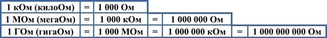
Первооткрывателей такого свойства электрической цепи, как сопротивление является выдающийся немецкий ученый Георг Симон Ом, поэтому за единицу измерения электрического сопротивления приняли Ом. Наиболее практическое применение получили килоомы, мегаомы и гигаомы.
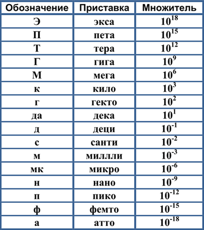
Расширенный список сокращений и приставок системы СИ физических величин, используемых в радиоэлектронике. Максимальное значение 1018 – экса, а минимальное – 10-18 – атто. Надеюсь, приведенная таблица станет полезной.
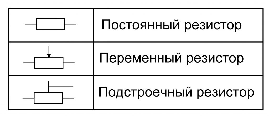
Условно резисторы подразделяются на два больших подвида: постоянные и переменные.
Постоянные резисторы
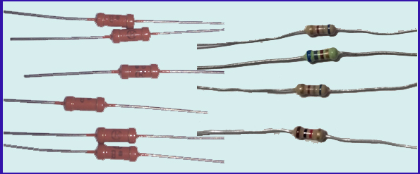
Постоянные резисторы могут иметь различное конструктивное исполнение, в основном отличающееся внешним видом и размерами. Характерной особенностью постоянных резисторов является постоянное значение сопротивления, которое не предусматривается изменять в процессе эксплуатации радиоэлектронной аппаратуры.
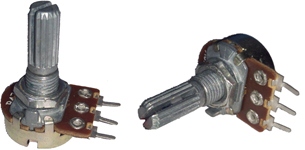
Подстроечные резисторы
Подстроечные резисторы применяются для тонкой настройки отдельных узлов радиоэлектронной аппаратуры на этапе ее окончательной регулировки перед выдачей в эксплуатацию. Чаще всего подстроечные резисторы не имеют специальной регулировочной рукоятки, а изменение сопротивления выполняется с помощью отвертки, что предотвращает самопроизвольное изменение положения регулировочного узла, а соответственно и сопротивления.
В некоторых устройствах после окончательной их регулировки на корпус и поворотный винт подстроечного резистора наносится краска, которая предотвращает поворот винта при наличии вибраций. Также метка, нанесенная краской, служит одновременно и индикатором самопроизвольного поворота регулировочного винта, что можно визуально определить по срыву краски в месте поворотного и стационарного элементов корпуса.
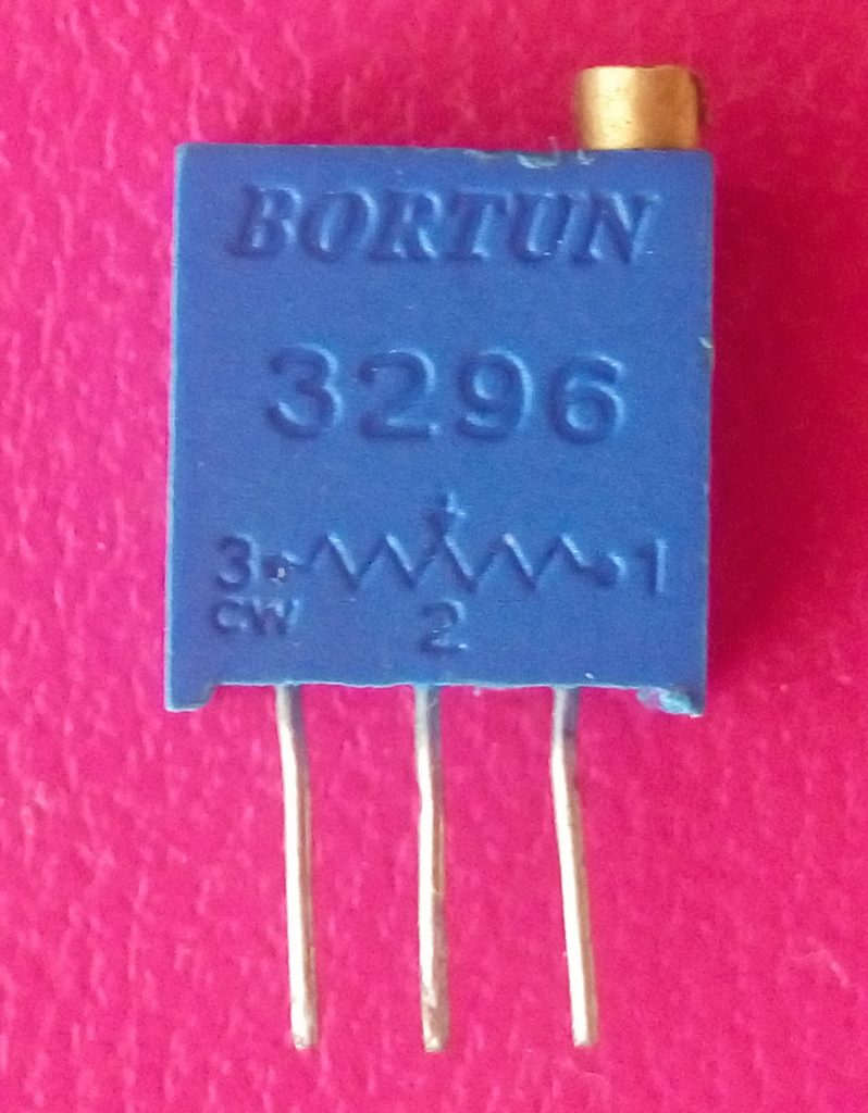
В современных электронных устройствах получили широкое применение многооборотные подстроечные резисторы, позволяющие более тонко выполнять регулировку аппаратуры. Как правило, они имеют синий пластиковый корпус прямоугольной формы.
Переменные резисторы
Переменные резисторы применяются для изменения электрических параметров в схеме устройства непосредственно в процессе работы, например для изменения яркости света светодиодных ламп или громкости звука приемника. Часто, вместо «переменный резистор» говорят потенциометр или реостат.
Также к переменным резисторам относятся радиоэлементы, имеющие всего два вывода, а сопротивление их изменяется в зависимости от освещенности или температуры, например фоторезисторы или терморезисторы.
Потенциометры применяются для изменения величины силы тока или напряжения. Регулируемый параметр зависит от схемы включения.
Если переменный либо подстроечный резистор используется в качестве регулятора тока, но его называют реостатом.
Ниже приведены две схемы, в которых реостат применяется для регулировки величины тока, протекающего через светодиод VD. В конечном итоге изменяется яркость свечения светодиода.
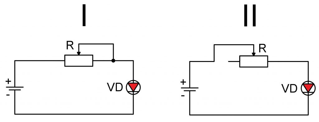
Обратите внимание, в первой цепи задействованы все три вывода реостата, а во второй – только два – средний (регулирующий) и один крайний. Обе схемы полностью работоспособны и выполняют возлагаемые на них функции. Однако вторую цепь применять менее предпочтительно, поскольку свободный вывод реостата, как антенна, может «поймать» различные электромагнитные излучения, что повлечет за собой изменение параметров электрической цепи. Особенно не рекомендуется применять такую электрическую цепь в усилительных каскадах, где даже незначительная электромагнитная наводка приведет к непредсказуемой работе аппаратуры. Поэтому берем за основу первую схему.
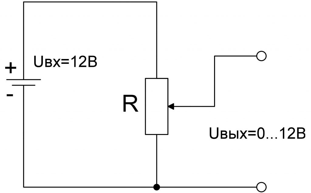
Изменять величину напряжения потенциометром можно по такой схеме: параллельно источнику питания подключается два крайних вывода; между одним крайним и средним выводами можно плавно регулировать напряжение от 0 до напряжения источника питания. В данном случае, от нуля до 12 В. Потенциометр служит делителем напряжения, которому более подробно уделено внимание в отдельной статье.
Условное графическое обозначение (УГО) резисторов
На чертежах электрических схем в независимости от внешнего вида резистора его обозначают прямоугольником. Прямоугольник подписывается латинской буквой R с цифрой, обозначающей порядковый номер данного элемента на чертеже. Ниже указывается номинальное значение сопротивления.
В некоторых государствах УГО резистора имеет следующий вид.

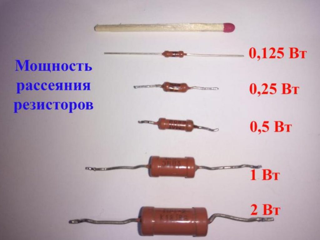
Мощность рассеивания резистора
Резистор, как и любой другой элемент, обладающий активным сопротивлением, подвержен нагреву при протекании через него тока. Природа нагрева заключается в том, что при движении электроны встречают на своем пути препятствия и ударяются об них. В результате столкновений кинетическая энергия электрона передается препятствиям, что вызывает нагрев последних. Аналогично нагревается гвоздь, когда по нему долго бьют молотком.
Мощность рассеивания нормируемый параметр для любого резистора и если ее не выдерживать, то он перегреется и сгорит.
Мощность рассеивания P линейно зависит от сопротивления R и в квадрате от тока I
P=I2R
Значение допустимой P показывает, какую мощность способен рассеять резистор не перегреваясь выше допустимой температуры в течение длительного времени.
Как правило, чем выше P, тем большие размеры имеет резистор, чтобы отвести и рассеять больше тепла.
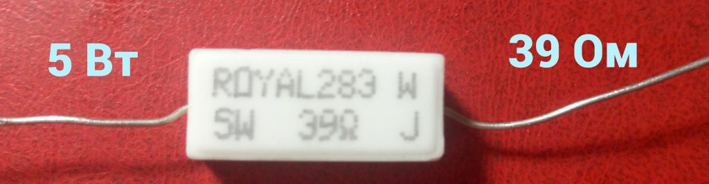
На чертежах электрических схем этот параметр наносится в виде определенных меток.
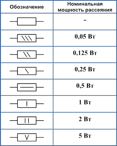
Если прямоугольник пустой – значит мощность рассеивания не нормирована, поэтому можно применять самый «маленький» резистор.
Более наглядные примеры расчета P можно посмотреть здесь.
Классы точности и номиналы резисторов
Ни один радиоэлектронный элемент невозможно выполнить со сто процентным соблюдением требуемых характеристик, так как точность связана с рядом параметров и технологических процессов, которым присуща погрешность, в основном связана с точностью производственного оборудования. Поэтому любая деталь или отдельный элемент имеют отклонение от заданных размеров или характеристик. Причем, чем меньший разброс характеристик, тем точнее производственное оборудование и выше конечная стоимость изделия. Поэтому далеко не всегда оправдано применение изделий с минимальными отклонениями характеристик. В связи с этим введены классы точности. В радиолюбительской практике наибольшее применение находят резисторы трех классов точности: I, II и III. Последним временем резисторы второго и третьего классов точности встречаются довольно редко, но мы их рассмотрим в качестве примера.
К I-му классу относится допуск отклонения сопротивления от номинального значения ±5%, II –му – ±10%, III –му – ±20%. Например, при номинальном значении сопротивления 100 Ом резистора I класса, допустимое отклонение может находиться в диапазоне 95…105 Ом; для II-го – 90…110 Ом; для III -го – 80…120 Ом.
Резисторы более высокого класса точности, с допуском 1% и менее, относятся к прецизионным. Они имеют более высокую стоимость, поэтому их применение оправдано только в измерительной и высокоточной технике.
Все стандартные значения сопротивлений I…III классов точности приведены выше в таблице, значения из которой могут умножаться на 0,1; 1, 10, 100, 1000 и т.д. Например, резисторы I-го класса изготавливаются со значениями 1,3; 13; 130; 1300; 13000; 130000 Ом и т.п.
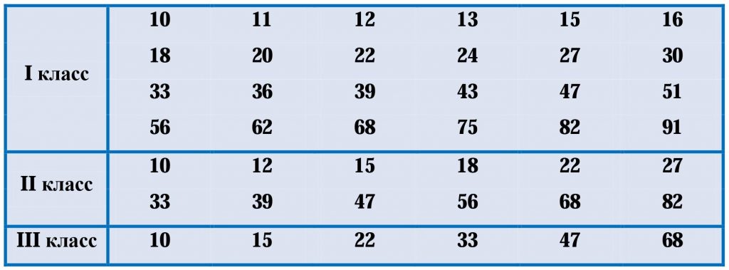
В зависимости от класса точности, номинальные значения выпускаемых промышленностью резисторов строго стандартизированы. Например, если потребуется сопротивление 17 Ом I-го класса, то вы его не найдете, поскольку данный номинал не изготавливается в соответствующем классе точности. Вместо него следует выбрать ближайший номинал – 16 Ом или 18 Ом.
Маркировка резисторов
Маркировка резисторов служит для визуального восприятия ряда параметров, характерных для данных электронных элементов. Среди прочих параметров следует выделить три основных: номинальное значение сопротивления, класс точности и мощность рассеивания. Именно на эти параметры в первую очередь обращают внимание при выборе рассматриваемых радиоэлементов.
На протяжении долгих лет существовало много типов маркировки, однако постепенно, по мере развития технологических процессов, пару типов маркировки вытеснили все остальные.
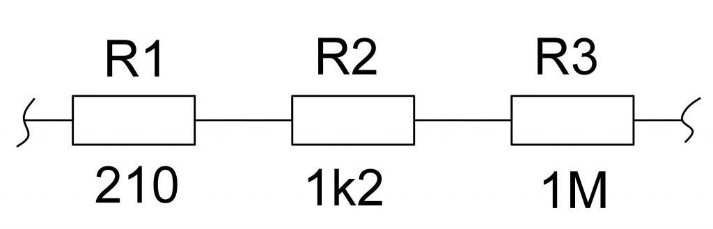
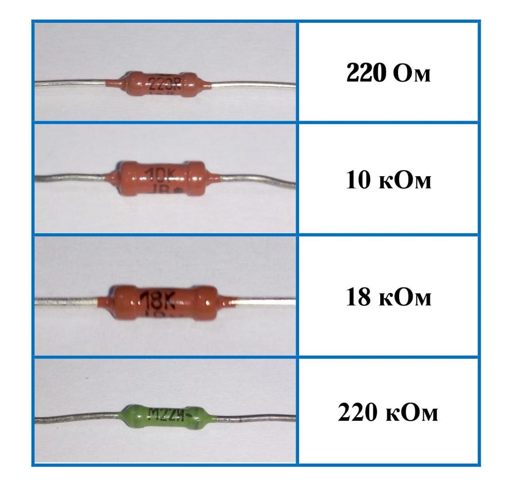
На корпусах советских резисторов, которые все еще широко используются, наносится маркировка в виде цифр и букв. Латинские буквы «E» и «R», стоящие рядом с цифрами или только цифры, обозначают сопротивление в омах, например 21; 21E, 21R – 21 Ом. Буквы «k» и «M» означают соответственно килоомы и мегаомы. Например, если буква стоит перед цифрами или посреди них, то она одновременно служит десятичной точкой: 68к – 68 кОм; 6к8 – 6,8 кОм; к68 – 0,68 кОм.
Цветовая маркировка резисторов
Для большинства радиоэлектронных элементов сейчас применяется цветовая маркировка. Такой подход является вполне рациональный, поскольку цветные метки проще рассмотреть, чем цифры и буквы, поэтому хорошо распознаются даже на самых мелких корпусах.
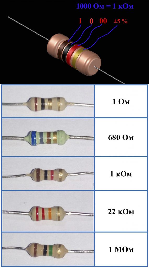
Цветная маркировка резисторов наносится на корпус в виде четырех или пяти цветных колец или полос. В первом случае (4 полосы) первые две полосы обозначают мантису, а во втором (5 полос) – мантису обозначают три полосы. Третье или соответственно 4-е кольцо указывают множитель. Четвертое или пятое – допустимое отклонение в процентах от номинального сопротивления.
По моему мнению и личному опыту, гораздо удобней, проще и практичней измерять сопротивление мультиметром. Здесь наименьшая вероятность допустить ошибку, поскольку цвета колец не всегда четко различимы. Например, красный цвет можно принять за оранжевый и наоборот. Однако, выполняя измерения, следует избегать касания пальцами щупов мультиметра и выводов резистора. В противном случае тело человека зашунтирует резистор, и результаты измерений будут заниженные.
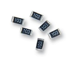
Маркировка SMD резисторов
Характерной особенностью SMD резисторов по сравнению с выводными аналогами являются минимальные габариты при сохранении необходимых характеристик.
В SMD компонентах отсутствуют гибкие выводы, вместо них имеются контактные площадки, посредством которых производится пайка SMD детали на аналогичные поверхности, предусмотренные на печатной плате. По этой причине SMD компоненты называют компонентами для поверхностного монтажа.
Благодаря смене традиционного корпуса на SMD упростился процесс автоматизации изготовления печатных плат, что позволило значительно снизить затраты время на изготовление электронного изделия, его массы и габаритов.
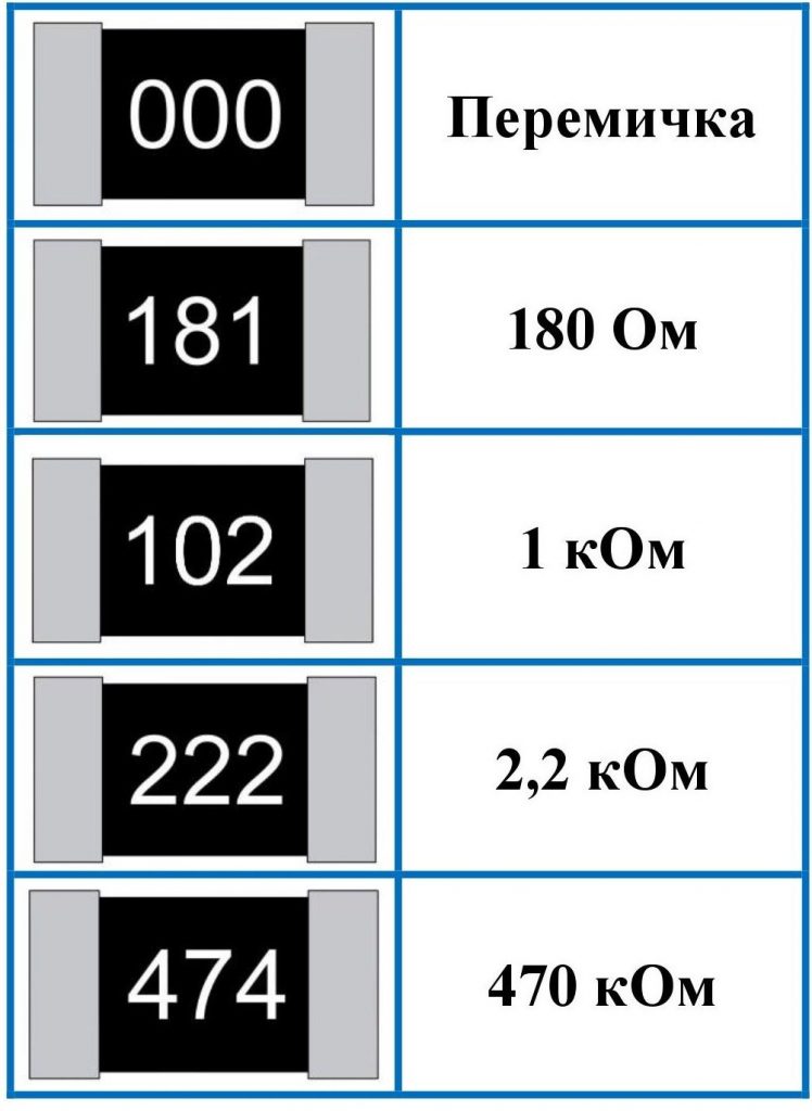
Маркировка SMD резисторов чаще всего состоит из трех цифр. Первые две указывают мантису ,а третья – множитель или количество нулей, следующих после двух предыдущих цифр. Например, маркировка 681 означает 68×101 = 680 Ом, то есть после числа 68 нужно прибавить один ноль.
Если все три цифры – нули, то это перемычка, сопротивление такого SMD резистора близкое к нулю.

Еще статьи по данной теме
90000 Resistors — learn.sparkfun.com 90001 Favorited Favorite 44 90002 Take a Stance, The Resist Stance 90003 90004 Resistors — the most ubiquitous of electronic components. They are a critical piece in just about every circuit. And they play a major role in our favorite equation, Ohm’s Law. 90005 90004 In this, our pièce de 90007 résistance 90008, we’ll cover: 90005 90010 90011 What is a resistor ?! 90012 90011 Resistor units 90012 90011 Resistor circuit symbol (s) 90012 90011 Resistors in series and parallel 90012 90011 Different variations of resistors 90012 90011 Color coding decoding 90012 90011 Surface mount resistor decoding 90012 90011 Example resistor applications 90012 90027 90028 Consider reading… 90029 90004 Some of the concepts in this tutorial build on previous electronics knowledge. Before jumping into this tutorial, consider reading (at least skimming) these first: 90005 90032 90002 Looking to get hands-on with resistors? 90003 90004 & nbsp 90005 90004 & nbsp 90005 90002 Resistor Basics 90003 90004 Resistors are electronic components which have a specific, never-changing electrical resistance. The resistor’s resistance 90042 limits the flow of electrons 90043 through a circuit.90005 90004 They are 90042 passive 90043 components, meaning they only consume power (and can not generate it). Resistors are usually added to circuits where they complement 90042 active 90043 components like op-amps, microcontrollers, and other integrated circuits. Commonly resistors are used to limit current, divide voltages, and pull-up I / O lines. 90005 90002 Resistor units 90003 90004 The electrical resistance of a resistor is measured in 90042 ohms 90043. The symbol for an ohm is the greek capital-omega: & ohm ;.The (somewhat roundabout) definition of 1 & ohm; is the resistance between two points where 1 volt (1V) of applied potential energy will push 1 ampere (1A) of current. 90005 90004 As SI units go, larger or smaller values of ohms can be matched with a prefix like kilo-, mega-, or giga-, to make large values easier to read. It’s very common to see resistors in the kilohm (k & ohm;) and megaohm (M & ohm;) range (much less common to see miliohm (m & ohm;) resistors). For example, a 4,700 & ohm; resistor is equivalent to a 4.7k & ohm; resistor, and a 5,600,000 & ohm; resistor can be written as 5,600k & ohm; or (more commonly as) 5.6M & ohm ;. 90005 90002 Schematic symbol 90003 90004 All resistors have 90042 two terminals 90043, one connection on each end of the resistor. When modeled on a schematic, a resistor will show up as one of these two symbols: 90005 90004 90007 Two common resistor schematic symbols. R1 is an American-style 1k & ohm; resistor, and R2 is an international-style 47k & ohm; resistor.90008 90005 90004 The terminals of the resistor are each of the lines extending from the squiggle (or rectangle). Those are what connect to the rest of the circuit. 90005 90004 The resistor circuit symbols are usually enhanced with both a resistance value and a name. The value, displayed in ohms, is obviously critical for both evaluating and actually constructing the circuit. The name of the resistor is usually an 90007 R 90008 preceding a number. Each resistor in a circuit should have a unique name / number.For example, here’s a few resistors in action on a 555 timer circuit: 90005 90004 90007 In this circuit, resistors play a key role in setting the frequency of the 555 timer’s output. Another resistor (R3) limits the current through an LED. 90008 90005 90032 90002 Types of Resistors 90003 90004 Resistors come in a variety of shapes and sizes. They might be through-hole or surface-mount. They might be a standard, static resistor, a pack of resistors, or a special variable resistor.90005 90002 Termination and Mounting 90003 90004 Resistors will come in one of two termination-types: through-hole or surface-mount. These types of resistors are usually abbreviated as either PTH (plated through-hole) or SMD / SMT (surface-mount technology or device). 90005 90004 90042 Through-hole 90043 resistors come with long, pliable leads which can be stuck into a breadboard or hand-soldered into a prototyping board or printed circuit board (PCB). These resistors are usually more useful in breadboarding, prototyping, or in any case where you’d rather not solder tiny, little 0.6mm-long SMD resistors. The long leads usually require trimming, and these resistors are bound to take up much more space than their surface-mount counterparts. 90005 90004 The most common through-hole resistors come in an axial package. The size of an axial resistor is relative to its power rating. A common ½W resistor measures about 9.2mm across, while a smaller ¼W resistor is about 6.3mm long. 90005 90004 90007 A half-watt (½W) resistor (above) sized up to a quarter-watt (¼W). 90008 90005 90004 90042 Surface-mount 90043 resistors are usually tiny black rectangles, terminated on either side with even smaller, shiny, silver, conductive edges.These resistors are intended to sit on top of PCBs, where they’re soldered onto mating landing pads. Because these resistors are so small, they’re usually set into place by a robot, and sent through an oven where solder melts and holds them in place. 90005 90004 90007 A tiny 0603 330 & ohm; resistor hovering over shiny George Washington’s nose on top of a [U.S. quarter] (http://en.wikipedia.org/wiki/Quarter_ (United_States_coin). 90008 90005 90004 SMD resistors come in standardized sizes; usually either 0805 (0.08 «long by 0.05» wide), 0603, or 0402. They’re great for mass circuit-board-production, or in designs where space is a precious commodity. They take a steady, precise hand to manually solder, though! 90005 90002 Resistor Composition 90003 90004 Resistors can be constructed out of a variety of materials. Most common, modern resistors are made out of either a 90042 carbon, metal, or metal-oxide film 90043. In these resistors, a thin film of conductive (though still resistive) material is wrapped in a helix around and covered by an insulating material.Most of the standard, no-frills, through-hole resistors will come in a carbon-film or metal-film composition. 90005 90004 90007 Peek inside the guts of a few carbon-film resistors. Resistance values from top to bottom: 27 & ohm ;, 330 & ohm; and a 3.3M & ohm ;. Inside the resistor, a carbon film is wrapped around an insulator. More wraps means a higher resistance. Pretty neat! 90008 90005 90004 Other through-hole resistors might be wirewound or made of super-thin metallic foil.These resistors are usually more expensive, higher-end components specifically chosen for their unique characteristics like a higher power-rating, or maximum temperature range. 90005 90004 Surface-mount resistors are usually either 90042 thick or thin-film 90043 variety. Thick-film is usually cheaper but less precise than thin. In both resistor types, a small film of resistive metal alloy is sandwiched between a ceramic base and glass / epoxy coating, and then connected to the terminating conductive edges.90005 90002 Special Resistor Packages 90003 90004 There are a variety of other, special-purpose resistors out there. Resistors may come in pre-wired packs of five-or-so resistor arrays. Resistors in these arrays may share a common pin, or be set up as voltage dividers. 90005 90004 90007 An array of five 330 & ohm; resistors, all tied together at one end. 90008 90005 90002 Variable Resistors (i.e. Potentiometers) 90003 90004 Resistors do not have to be static either. Variable resistors, known as 90042 rheostats 90043, are resistors which can be adjusted between a specific range of values.Similar to the rheostat is the 90042 potentiometer 90043. Pots connect two resistors internally, in series, and adjust a center tap between them creating an adjustable voltage divider. These variable resistors are often used for inputs, like volume knobs, which need to be adjustable. 90005 90032 90002 Decoding Resistor Markings 90003 90004 Though they may not display their value outright, most resistors are marked to show what their resistance is. PTH resistors use a color-coding system (which really adds some flair to circuits), and SMD resistors have their own value-marking system.90005 90002 Decoding the Color Bands 90003 90004 Through-hole, axial resistors usually use the color-band system to display their value. Most of these resistors will have four bands of color circling the resistor, though you will also find five band and six band resistors. 90005 90028 Four Band Resistors 90029 90004 In the standard four band resistors, the first two bands indicate the 90042 two most-significant digits 90043 of the resistor’s value. The third band is a weight value, which 90042 multiplies 90043 the two significant digits by a power of ten.90005 90004 The final band indicates the 90042 tolerance 90043 of the resistor. The tolerance explains how much more or less the 90007 actual 90008 resistance of the resistor can be compared to what its nominal value is. No resistor is made to perfection, and different manufacturing processes will result in better or worse tolerances. For example, a 1k & ohm; resistor with 5% tolerance could actually be anywhere between 0.95k & ohm; and 1.05k & ohm ;. 90005 90004 How do you tell which band is first and last? The last, tolerance band is often clearly separated from the value bands, and usually it’ll either be silver or gold.90005 90028 Five and Six Band Resistors 90029 90004 Five band resistors have a third significant digit band between the first two bands and the 90042 multiplier band 90043. Five band resistors also have a wider range of tolerances available. 90005 90004 Six band resistors are basically five band resistors with an additional band at the end that indicates the temperature coefficient. This indicates the expected change in resistor value as the temperature changes in degrees Celsius. Generally these temperature coefficient values are extremely small, in the ppm range.90005 90028 Decoding Resistor Color Bands 90029 90004 When decoding the resistor color bands, consult a resistor color code table like the one below. For the first two bands, find that color’s corresponding digit value. The 4.7k & ohm; resistor shown here has color bands of yellow and violet to begin — which have digit values of 4 and 7 (47). The third band of the 4.7k & ohm; is red, which indicates that the 47 should be multiplied by 10 90 176 2 90 177 (or 100). 47 times 100 is 4,700! 90005 90004 90007 4.7k & ohm; resistor with four color bands 90008 90005 90004 If you’re trying to commit the color band code to memory, a mnemonic device might help. There are a handful of (sometimes unsavory) mnemonics out there to help remember the resistor color code. A good one, which spells out the difference between 90007 b 90008 lack and 90007 b 90008 rown is: 90005 90004 «90190 B 90191 ig 90190 b 90191 rown 90190 r 90191 abbits 90190 o 90191 ften 90190 y 90191 ield 90190 g 90191 reat 90190 b 90191 ig 90190 v 90191 ocal 90190 g 90191 roans 90190 w 90191 hen 90190 g 90191 ingerly 90190 s 90191 napped .»90005 90004 Or, if you remember «ROY G. BIV», subtract the 90007 indigo 90008 (poor indigo, no one remembers indigo), and add black and brown to the front and gray and white to the back of the classic rainbow color-order . 90005 90028 Resistor Color Code Table 90029 90004 90007 Having trouble seeing? Click the image for a better view! 90008 90005 90028 Resistor Color Code Calculator 90029 90004 If you’d rather skip the math (we will not judge!), And just use a handy calculator, give one of these a try! 90005 90229 Four Band Resistors 90230 90231 90232 90233 Band 1 90234 90233 Band 2 90234 90233 Band 3 90234 90239 90233 Band 4 90234 90242 90232 90233 Value 1 (MSV) 90234 90233 Value 2 90234 90233 Weight 90234 90239 90233 Tolerance 90234 90242 90254 90233 Black (0) Brown (1) Red (2) Orange (3) Yellow (4) Green (5) Blue (6) Violet (7) Gray (8) White (9) 90234 90233 Black (0) Brown (1) Red (2) Orange (3) Yellow (4) Green (5) Blue (6) Violet (7) Gray (8) White (9) 90234 90233 Black (1) Brown (10) Red (100) Orange (1k) Yellow (10k) Green (100k) Blue (1M) Violet (10M) Gray (100M) White (1G) 90234 90233 90234 90233 Gold (± 5%) Silver (± 10%) 90234 90242 90266 90028 Resistance: 1 k & ohm; ± 5% 90029 90229 Five and Six Band Resistors 90230 90190 Note: 90191 Calculate your six band resistor here, but be sure to append the temperature coefficient to the final value of the resistor.90231 90232 90233 Band 1 90234 90233 Band 2 90234 90233 Band 3 90234 90233 Band 4 90234 90239 90233 Band 5 90234 90242 90232 90233 Value 1 (MSV) 90234 90233 Value 2 90234 90233 Value 3 90234 90233 Weight 90234 90239 90233 Tolerance 90234 90242 90254 90233 Black (0) Brown (1) Red (2) Orange (3) Yellow (4) Green (5) Blue (6) Violet (7) Gray (8) White (9) 90234 90233 Black (0) Brown (1) Red (2) Orange (3) Yellow (4) Green (5) Blue (6) Violet (7) Gray (8) White (9) 90234 90233 Black (0) Brown (1) Red (2) Orange (3) Yellow (4) Green (5) Blue (6) Violet (7) Gray (8) White (9) 90234 90233 Black (1) Brown (10) Red (100) Orange (1k) Yellow (10k) Green (100k) Blue (1M) Violet (10M) Gray (100M) White (1G) 90234 90233 90234 90233 Gold (± 5%) Silver (± 10%) Brown (± 1%) Red (± 2%) Green (± 0.5%) Blue (± 0.25%) Violet (± 0.1%) Gray (± 0.05%) 90234 90242 90266 90028 Resistance: 1 k & ohm; ± 5% 90029 90002 Decoding Surface-Mount Markings 90003 90004 SMD resistors, like those in 0603 or 0805 packages, have their own way of displaying their value. There are a few common marking methods you’ll see on these resistors. They’ll usually have three to four characters — numbers or letters — printed on top of the case. 90005 90004 If the three characters you’re seeing are 90007 all numbers 90008, you’re probably looking at an 90042 E24 90043 marked resistor.These markings actually share some similarity with the color-band system used on the PTH resistors. The first two numbers represent the first two most-significant digits of the value, the last number represents a magnitude. 90005 90004 In the above example picture, resistors are marked 90007 104 90008, 90007 105 90008, 90007 205 90008, 90007 751 90008, and 90007 754 90008. The resistor marked with 90007 104 90008 should be 100k & ohm; (10×10 90176 4 90177), 90007 105 90008 would be 1M & ohm; (10×10 90176 5 90177), and 90007 205 90008 is 2M & ohm; (20×10 90176 5 90177).90007 751 90008 is 750 & ohm; (75×10 90176 1 90177), and 90007 754 90008 is 750k & ohm; (75×10 90176 4 90177). 90005 90004 Another common coding system is 90042 E96 90043, and it’s the most cryptic of the bunch. E96 resistors will be marked with three characters — two numbers at the beginning and a letter at the end. The two numbers tell you the first 90007 three 90008 digits of the value, by corresponding to one of the not-so-obvious values on this lookup table. 90005 90365 90366 90367 90367 90367 90367 90367 90367 90367 90367 90367 90367 90367 90367 90367 90367 90367 90367 90367 90384 90254 90386 Code 90387 90386 Value 90387 90386 90391 90387 90386 Code 90387 90386 Value 90387 90386 90391 90387 90386 Code 90387 90386 Value 90387 90386 90391 90387 90386 Code 90387 90386 Value 90387 90386 90391 90387 90386 Code 90387 90386 Value 90387 90386 90391 90387 90386 Code 90387 90386 Value 90387 90242 90232 90233 01 90234 90233 100 90234 90233 90391 90234 90233 17 90234 90233 147 90234 90233 90391 90234 90233 33 90234 90233 215 90234 90233 90391 90234 90233 49 90234 90233 316 90234 90233 90391 90234 90233 65 90234 90233 464 90234 90233 90391 90234 90233 81 90234 90233 681 90234 90242 90232 90233 02 90234 90233 102 90234 90233 90391 90234 90233 18 90234 90233 150 90234 90233 90391 90234 90233 34 90234 90233 221 90234 90233 90391 90234 90233 50 90234 90233 324 90234 90233 90391 90234 90233 66 90234 90233 475 90234 90233 90391 90234 90233 82 90234 90233 698 90234 90242 90232 90233 03 90234 90233 105 90234 90233 90391 90234 90233 19 90234 90233 154 90234 90233 90391 90234 90233 35 90234 90233 226 90234 90233 90391 90234 90233 51 90234 90233 332 90234 90233 90391 90234 90233 67 90234 90233 487 90234 90233 90391 90234 90233 83 90234 90233 715 90234 90242 90232 90233 04 90234 90233 107 90234 90233 90391 90234 90233 20 90234 90233 158 90234 90233 90391 90234 90233 36 90234 90233 232 90234 90233 90391 90234 90233 52 90234 90233 340 90234 90233 90391 90234 90233 68 90234 90233 499 90234 90233 90391 90234 90233 84 90234 90233 732 90234 90242 90232 90233 05 90234 90233 110 90234 90233 90391 90234 90233 21 90234 90233 162 90234 90233 90391 90234 90233 37 90234 90233 237 90234 90233 90391 90234 90233 53 90234 90233 348 90234 90233 90391 90234 90233 69 90234 90233 511 90234 90233 90391 90234 90233 85 90234 90233 750 90234 90242 90232 90233 06 90234 90233 113 90234 90233 90391 90234 90233 22 90234 90233 165 90234 90233 90391 90234 90233 38 90234 90233 243 90234 90233 90391 90234 90233 54 90234 90233 357 90234 90233 90391 90234 90233 70 90234 90233 523 90234 90233 90391 90234 90233 86 90234 90233 768 90234 90242 90232 90233 07 90234 90233 115 90234 90233 90391 90234 90233 23 90234 90233 169 90234 90233 90391 90234 90233 39 90234 90233 249 90234 90233 90391 90234 90233 55 90234 90233 365 90234 90233 90391 90234 90233 71 90234 90233 536 90234 90233 90391 90234 90233 87 90234 90233 787 90234 90242 90232 90233 08 90234 90233 118 90234 90233 90391 90234 90233 24 90234 90233 174 90234 90233 90391 90234 90233 40 90234 90233 255 90234 90233 90391 90234 90233 56 90234 90233 374 90234 90233 90391 90234 90233 72 90234 90233 549 90234 90233 90391 90234 90233 88 90234 90233 806 90234 90242 90232 90233 09 90234 90233 121 90234 90233 90391 90234 90233 25 90234 90233 178 90234 90233 90391 90234 90233 41 90234 90233 261 90234 90233 90391 90234 90233 57 90234 90233 383 90234 90233 90391 90234 90233 73 90234 90233 562 90234 90233 90391 90234 90233 89 90234 90233 825 90234 90242 90232 90233 10 90234 90233 124 90234 90233 90391 90234 90233 26 90234 90233 182 90234 90233 90391 90234 90233 42 90234 90233 267 90234 90233 90391 90234 90233 58 90234 90233 392 90234 90233 90391 90234 90233 74 90234 90233 576 90234 90233 90391 90234 90233 90 90234 90233 845 90234 90242 90232 90233 11 90234 90233 127 90234 90233 90391 90234 90233 27 90234 90233 187 90234 90233 90391 90234 90233 43 90234 90233 274 90234 90233 90391 90234 90233 59 90234 90233 402 90234 90233 90391 90234 90233 75 90234 90233 590 90234 90233 90391 90234 90233 91 90234 90233 866 90234 90242 90232 90233 12 90234 90233 130 90234 90233 90391 90234 90233 28 90234 90233 191 90234 90233 90391 90234 90233 44 90234 90233 280 90234 90233 90391 90234 90233 60 90234 90233 412 90234 90233 90391 90234 90233 76 90234 90233 604 90234 90233 90391 90234 90233 92 90234 90233 887 90234 90242 90232 90233 13 90234 90233 133 90234 90233 90391 90234 90233 29 90234 90233 196 90234 90233 90391 90234 90233 45 90234 90233 287 90234 90233 90391 90234 90233 61 90234 90233 422 90234 90233 90391 90234 90233 77 90234 90233 619 90234 90233 90391 90234 90233 93 90234 90233 909 90234 90242 90232 90233 14 90234 90233 137 90234 90233 90391 90234 90233 30 90234 90233 200 90234 90233 90391 90234 90233 46 90234 90233 294 90234 90233 90391 90234 90233 62 90234 90233 432 90234 90233 90391 90234 90233 78 90234 90233 634 90234 90233 90391 90234 90233 94 90234 90233 931 90234 90242 90232 90233 15 90234 90233 140 90234 90233 90391 90234 90233 31 90234 90233 205 90234 90233 90391 90234 90233 47 90234 90233 301 90234 90233 90391 90234 90233 63 90234 90233 442 90234 90233 90391 90234 90233 79 90234 90233 649 90234 90233 90391 90234 90233 95 90234 90233 953 90234 90242 90232 90233 16 90234 90233 143 90234 90233 90391 90234 90233 32 90234 90233 210 90234 90233 90391 90234 90233 48 90234 90233 309 90234 90233 90391 90234 90233 64 90234 90233 453 90234 90233 90391 90234 90233 80 90234 90233 665 90234 90233 90391 90234 90233 96 90234 90233 976 90234 90242 90266 90004 The letter at the end represents a multiplier, matching up to something on this table: 90005 90365 90366 90367 90367 90367 90367 90367 90367 90367 90367 90384 90254 90386 Letter 90387 90386 Multiplier 90387 91101 90386 Letter 90387 90386 Multiplier 90387 91101 90386 Letter 90387 90386 Multiplier 90387 90242 90232 90233 Z 90234 90233 0.001 90234 90239 90233 A 90234 90233 1 90234 90239 90233 D 90234 90233 1000 90234 90242 90232 90233 Y or R 90234 90233 0.01 90234 90239 90233 B or H 90234 90233 10 90234 90239 90233 E 90234 90233 10000 90234 90242 90232 90233 X or S 90234 90233 0.1 90234 90239 90233 C 90234 90233 100 90234 90239 90233 F 90234 90233 100000 90234 90242 90266 90004 So a 90007 01C 90008 resistor is our good friend, 10k & ohm; (100×100), 90007 01B 90008 is 1k & ohm; (100×10), and 90007 01D 90008 is 100k & ohm ;.Those are easy, other codes may not be. 90007 85A 90008 from the picture above is 750 & ohm; (750×1) and 90007 30C 90008 is actually 20k & ohm ;. 90005 90032 90002 Power Rating 90003 90004 The power rating of a resistor is one of the more hidden values. Nevertheless it can be important, and it’s a topic that’ll come up when selecting a resistor type. 90005 90004 Power is the rate at which energy is transformed into something else. It’s calculated by multiplying the voltage difference across two points by the current running between them, and is measured in units of a watt (W).Light bulbs, for example, power electricity into light. But a resistor can only turn electrical energy running through it into 90042 heat 90043. Heat is not usually a nice playmate with electronics; too much heat leads to smoke, sparks, and fire! 90005 90004 Every resistor has a specific maximum power rating. In order to keep the resistor from heating up too much, it’s important to make sure the power across a resistor is kept under it’s maximum rating. The power rating of a resistor is measured in watts, and it’s usually somewhere between & frac18; W (0.125W) and 1W. Resistors with power ratings of more than 1W are usually referred to as power resistors, and are used specifically for their power dissipating abilities. 90005 90002 Finding a resistor’s power rating 90003 90004 A resistor’s power rating can usually be deduced by observing its package size. Standard through-hole resistors usually come with ¼W or ½W ratings. More special purpose, power resistors might actually list their power rating on the resistor. 90005 90004 90007 These power resistors can handle a lot more power before they blow.From top-right to bottom-left there are examples of 25W, 5W and 3W resistors, with values of 2 & ohm ;, 3 & ohm; 0.1 & ohm; and 22k & ohm ;. Smaller power-resistors are often used to sense current. 90008 90005 90004 The power ratings of surface mount resistors can usually be judged by their size as well. Both 0402 and 0603-size resistors are usually rated for 1 / 16W, and 0805’s can take 1 / 10W. 90005 90002 Measuring power across a resistor 90003 90004 Power is usually calculated by multiplying voltage and current (P = IV).But, by applying Ohm’s law, we can also use the resistance value in calculating power. If we know the current running through a resistor, we can calculate the power as: 90005 90004 Or, if we know the voltage across a resistor, the power can be calculated as: 90005 90032 90002 Series and Parallel Resistors 90003 90004 Resistors are paired together all the time in electronics, usually in either a series or parallel circuit. When resistors are combined in series or parallel, they create a 90042 total resistance 90043, which can be calculated using one of two equations.Knowing how resistor values combine comes in handy if you need to create a specific resistor value. 90005 90002 Series resistors 90003 90004 When connected in series resistor values simply add up. 90005 90004 90007 N resistors in series. The total resistance is the sum of all series resistors. 90008 90005 90004 So, for example, if you just 90007 have to have 90008 a 12.33k & ohm; resistor, seek out some of the more common resistor values of 12k & ohm; and 330 & ohm ;, and butt them up together in series.90005 90002 Parallel resistors 90003 90004 Finding the resistance of resistors in parallel is not quite so easy. The total resistance of 90007 N 90008 resistors in parallel is the inverse of the sum of all inverse resistances. This equation might make more sense than that last sentence: 90005 90004 90007 N resistors in parallel. To find the total resistance, invert each resistance value, add them up, and then invert that. 90008 90005 90004 (The inverse of resistance is actually called 90042 conductance 90043, so put more succinctly: the 90007 conductance 90008 of parallel resistors is the sum of each of their conductances).90005 90004 As a special case of this equation: if you have 90042 just two 90043 resistors in parallel, their total resistance can be calculated with this slightly-less-inverted equation: 90005 90004 As an even 90007 more special 90008 case of that equation, if you have two parallel resistors of 90042 equal value 90043 the total resistance is half of their value. For example, if two 10k & ohm; resistors are in parallel, their total resistance is 5k & ohm ;. 90005 90004 A shorthand way of saying two resistors are in parallel is by using the parallel operator: 90042 || 90043.For example, if R 91248 1 91249 is in parallel with R 91248 2 91249, the conceptual equation could be written as R 91248 1 91249 || R 91248 2 91249. Much cleaner, and hides all those nasty fractions! 90005 90002 Resistor networks 90003 90004 As a special introduction to calculating total resistances, electronics teachers just 90007 love 90008 to subject their students to finding that of crazy, convoluted resistor networks. 90005 90004 A tame resistor network question might be something like: «what’s the resistance from terminals 90007 A 90008 to 90007 B 90008 in this circuit?» 90005 90004 To solve such a problem, start at the back-end of the circuit and simplify towards the two terminals.In this case R 91248 7 91249, R 91248 8 91249 and R 91248 9 91249 are all in series and can be added together. Those three resistors are in parallel with R 91248 6 91249, so those four resistors could be turned into one with a resistance of R 91248 6 91249 || (R 91248 7 91249 + R 91248 8 91249 + R 91248 9 91249). Making our circuit: 90005 90004 Now the four right-most resistors can be simplified even further. R 91248 4 91249, R 91248 5 91249 and our conglomeration of R 91248 6 91249 — R 91248 9 91249 are all in series and can be added.Then those series resistors are all in parallel with R 91248 3 91249. 90005 90004 And that’s just three series resistors between the 90007 A 90008 and 90007 B 90008 terminals. Add ’em on up! So the total resistance of that circuit is: R 91248 1 91249 + R 91248 2 91249 + R 91248 3 91249 || (R 91248 4 91249 + R 91248 5 91249 + R 91248 6 91249 || (R 91248 7 91249 + R 91248 8 91249 + R 91248 9 91249)). 90005 90032 90002 Example Applications 90003 90004 Resistors exist in just about every electronic circuit ever.Here are a few examples of circuits, which heavily depend on our resistor friends. 90005 90004 Resistors are key in making sure LEDs do not blow up when power is applied. By connecting a resistor 90042 in series 90043 with an LED, current flowing through the two components can be limited to a safe value. 90005 90004 When sizing out a current-limiting resistor, look for two characteristic values of the LED: the 90042 typical forward voltage 90043, and the 90042 maximum forward current 90043.The typical forward voltage is the voltage which is required to make an LED light up, and it varies (usually somewhere between 1.7V and 3.4V) depending upon the color of the LED. The maximum forward current is usually around 20mA for basic LEDs; continuous current through the LED should always be equal to or less than that current rating. 90005 90004 Once you’ve gotten ahold of those two values, you can size up a current-limiting resistor with this equation: 90005 90004 V 91248 S 91249 is the source voltage — usually a battery or power supply voltage.V 91248 F 91249 and I 91248 F 91249 are the LED’s forward voltage and the desired current that runs through it. 90005 90004 For example, assume you have a 9V battery to power an LED. If your LED is red, it might have a forward voltage around 1.8V. If you want to limit the current to 10mA, use a series resistor of about 720 & ohm ;. 90005 90002 Voltage Dividers 90003 90004 A voltage divider is a resistor circuit which turns a large voltage into a smaller one. Using just two resistors in series, an output voltage can be created that’s a fraction of the input voltage.90005 90004 Here’s the voltage divider circuit: 90005 90004 Two resistors, R 91248 1 91249 and R 91248 2 91249, are connected in series and a voltage source (V 91248 in 91249) is connected across them. The voltage from V 91248 out 91249 to GND can be calculated as: 90005 90004 For example, if R 91248 1 91249 was 1.7k & ohm; and R 91248 2 91249 was 3.3k & ohm ;, a 5V input voltage could be turned into 3.3V at the V 91248 out 91249 terminal. 90005 90004 Voltage dividers are very handy for reading resistive sensors, like photocells, flex sensors, and force-sensitive resistors.One half of the voltage divider is the sensor, and the part is a static resistor. The output voltage between the two components is connected to an analog-to-digital converter on a microcontroller (MCU) to read the sensor’s value. 90005 90004 90007 Here a resistor R 91248 1 91249 and a photocell create a voltage divider to create a variable voltage output. 90008 90005 90002 Pull-up Resistors 90003 90004 A pull-up resistor is used when you need to bias a microcontroller’s input pin to a known state.One end of the resistor is connected to the MCU’s pin, and the other end is connected to a high voltage (usually 5V or 3.3V). 90005 90004 Without a pull-up resistor, inputs on the MCU could be left 90007 floating 90008. There’s no guarantee that a floating pin is either high (5V) or low (0V). 90005 90004 Pull-up resistors are often used when interfacing with a button or switch input. The pull-up resistor can bias the input-pin when the switch is open. And it will protect the circuit from a short when the switch is closed.90005 90004 In the circuit above, when the switch is open the MCU’s input pin is connected through the resistor to 5V. When the switch closes, the input pin is connected directly to GND. 90005 90004 The value of a pull-up resistor does not usually need to be anything specific. But it should be high enough that not too much power is lost if 5V or so is applied across it. Usually values around 10k & ohm; work well. 90005 90032 90002 Purchasing Resistors 90003 90004 Do not limit your flow of resistors.We’ve got kits, packs, single pieces, and tools that you just can not 90007 resist 90008. 90005 90028 Our Recommendations: 90029 Click Here to View More Resistors in the Catalog 90229 Tools: 90230 90028 Digital Multimeter — Basic 90029 In stock TOL-12966 90004 The digital multimeter (DMM) is an essential tool in every electronic enthusiasts arsenal.The SparkFun Digital Multimeter, h … 90005 21 90028 Resistor Lead Bending Tool 90029 In stock TOL-13114 90004 This little piece of notched plastic is a Resistor Lead Bending Tool. Sometimes referred to as a «forming» tool, this little … 90005 2 90032 90002 Resources and Going Further 90003 90004 Now that you’re a budding expert on all things resistor, how ’bout exploring some more fundamental electronics concepts! Resistors certainly are not the only basic component we use in electronics, there’s also: 90005 90004 Or maybe you’d like to further explore resistor applications? 90005 90004 90005 90004 90005 .90000 Basics: Picking Resistors for LEDs 90001 90002 90003 90004 90002 So … you just want to light up an LED. What resistor should you use? 90004 90002 Maybe you know the answer, or maybe everyone already assumes that you should know how to get to the answer. And in any case, it’s a question that tends to generate more questions before you actually can get an answer: What kind of LED are you using? What power supply? Battery? Plug-in? Part of a larger circuit? Series? Parallel? 90004 90002 Playing with LEDs is supposed to be fun, and figuring out the answers to these questions is actually part of the fun.There’s a simple formula that you use for figuring it out, Ohm’s Law. That formula is 90010 V 90011 = 90010 I 90011 × 90010 R 90011, where 90010 V 90011 is the voltage, 90010 I 90011 is the current, and 90010 R 90011 is the resistance. But how do you know what numbers to plug into that formula to get out the right resistor value? 90004 90002 To get the 90010 V 90011 in our formula, we need to know two things: the voltage of our power supply, and the voltage of our LEDs. 90004 90002 Lets start with a concrete example.Suppose that we are using a 2 × AA battery holder (like this one from our shop), which will provide us with a 3 V of power (with two 1.5 V AA cells in series; we add the voltages), and we’ll plan to hook up a yellow LED (like one of these). 90004 90002 LEDs have a characteristic called «forward voltage» which is often shown on the datasheets as Vf. This forward voltage is the amount of voltage «lost» in the LED when operated at a certain reference current, usually defined to be about 20 milliamps (mA), i.e., 0.020 amps (A). Vf depends primarily on the color of the LED, but actually varies a bit from LED to LED, sometimes even within the same bag of LEDs. Standard red, orange, yellow and yellow-green LEDs have a Vf of about 1.8 V, while pure-green, blue, white, and UV LEDs have a Vf of about 3.3 V. So, the voltage drop from our yellow LED will be about 1.8 V. 90004 90002 The 90010 V 90011 in our formula is found by subtracting the LED’s forward voltage from the voltage of the power supply. 90004 90002 3 V (power source) — 1.8 V (LED voltage drop) = 1.2 V 90004 90002 In this case, we’re left with 1.2 V which we’ll plug into our 90010 V 90011 = 90010 I 90011 × 90010 R 90011 formula. 90004 90002 The next thing we need to know is the 90010 I 90011, which is current we want to drive the LED at. LEDs have a maximum continuous current rating (often listed as If, or Imax on datasheets). This is often around 25 or 30 mA. What this really means is that a typical current value to aim for with a standard LED is 20 mA to 25 mA-slightly under the maximum current.90004 90002 90010 Aside: 90011 You can always give an LED 90010 less current 90011. Running an LED near its rated maximum current gives you maximum brightness, at the cost of power dissipation (heat) and battery life (if you’re running off of batteries, of course.) If you want your batteries to last ten times longer, you can usually just pick a current that is only one tenth of the rated maximum current. 90004 90002 So, 25 mA is the «desired» current- what we’re hoping to get when we pick a resistor, and also the 90010 I 90011 that we’ll plug into our 90010 V 90011 = 90010 I 90011 × 90010 R 90011 formula .90004 90002 1.2 V = 25 mA × 90010 R 90011 90004 90002 or rephrased: 90004 90002 1.2 V / 25 mA = 90010 R 90011 90004 90002 and when we solve that we get: 90004 90002 1.2 V / 25 mA = 1.2 V / 0.025 A = 48 Ω 90004 90002 Where «48 Ω» is 48 ohms. (The units are such that 1 V / 1 A = 1 Ω; one volt divided by one amp equals one ohm. If you are dealing with current in mA, convert to A by dividing by 1000.) 90004 90002 Our version of the formula now looks like this: 90004 90002 (Power supply voltage — LED voltage) / current (in amps) = desired resistor value (in ohms) 90004 90002 We end up with a resistor value of 48 Ω.And, that’s a fine starting resistor value for use with a yellow LED and a 3 V source. 90004 90002 Let’s look at resistor values for a moment. Resistors are usually available in values such as 10 Ω, 12 Ω, 15 Ω, 18 Ω, 22 Ω, 27 Ω, 33 Ω, 39 Ω, 47 Ω, 51 Ω, 56 Ω, 68 Ω, 75 Ω, and 82 Ω (and their multiples, 510 Ω, 5.1K Ω, 51K Ω, etc.), and (unless you specify higher precision while shopping) have a tolerance value of about ± 5%. 90004 90002 If you do a lot of electronics projects, you’re likely to have a bunch of resistors lying around.If you’re just getting started, you might want to get an assortment so that you have some handy. Resistors also come rated to handle varying amounts of power- resistors rated for more power (more watts) are able to safely dissipate more heat generated within the resistor. 1/4 watt resistors are probably the most common, and are generally just fine for simple LED circuits like the ones we’re covering here. (We’ve discussed power dissipation previously-look into that when you start to move beyond these basics.) 90004 90002 Now, the resistor value we calculated above was 48 Ω, which is not one of our common values. But that’s okay, because we’ll be using a resistor with a ± 5% tolerance, so it will not necessarily be exactly that value anyway. To be on the safe side, we generally select the next higher value that we have on hand; 51 Ω in this example. 90004 90002 Lets hook this up: 90094 3 V battery box, 51 Ω resistor, and yellow LED. 90004 90002 90004 90002 Now, that’s a nice little LED circuit, but how can we do this with more LEDs? Can we just add another resistor and another LED? Well, yes, to a point.Each LED will want 25 mA, so we need to figure out how much current our batteries can source. 90004 90002 90010 Aside 90011: A little digging turns up a helpful technical handbook (pdf) on alkaline batteries from Energizer. It turns out that the harder you drive them, the faster you drain them. 90010 Part of this 90011 is obvious: If you continuously draw 1000 mA out of a battery, you would expect the battery to last 1/10 as long as if you draw 100 mA. But there’s actually a second effect, which is that the total energy output the battery (measured in watt-hours) decreases when you approach the limit of how much current the battery can source.In practice, with AA alkaline batteries, if you drain it at 1000 mA, it will only last about 1/20 as long as it would if you drained it at 100 mA. 90004 90002 For our single 25 mA LED, AA cells will last a heck of a long time. If we run four LEDs in parallel, requiring 100 mA, we should still get pretty decent battery life. For higher than 500 mA, we should think about plugging into the wall. So, we can add several of our yellow LEDs, each with its own 51 Ω resistor, and drive them happily with a 2xAA battery holder.90004 90002 90004 90002 All right, how about a 9 V battery? Let’s stick with our yellow LEDs. If we want to run one LED off of a 9 V battery, that means we have to take up a whopping 7.2 V with our resistor, which would need to be 288 Ω (or the nearest convenient value: 330 Ω, in my workshop) . 90004 90002 9 V (power supply) — 1.8 V (yellow LED) = 7.2 V 90004 90002 7.2 V / 25 mA = 288 Ω (round up to 330 Ω) 90004 90002 Using a resistor for a voltage drop of any size dissipates that energy in the form of heat.That means that we’re just wasting that energy on heat instead of getting more light out of our LED circuit. So can we use multiple LEDs strung together? Yes! Let’s put four of the 1.8 V LEDs in series, adding up to a total of 7.2 V. When we subtract that from our supply voltage of 9 V, we’re left with 1.8 V, requiring only a 72 Ω resistor (or nearest value : 75 Ω). 90004 90002 9 V — (1.8 V × 4) = 9 V — 7.2 V = 1.8 V 90004 90002 1.8 V / 25 mA = 72 Ω (and we then round up to 75 Ω) 90004 90002 Our generalized version of the formula with multiple LEDs in series is: 90004 90002 [Power supply voltage — (LED voltage × number of LEDs)] / current = resistor value 90004 90002 We can even put a couple of these strings of four LEDs plus a resistor in parallel to get more light output, but the more we add, the more we’ll shorten our battery life.90004 90002 But can we do five in series with a 9 V battery? Well, maybe. The 1.8 V figure that we’ve been using is a «typical rule of thumb,» only. If you’re sure the forward voltage is exactly 1.8 V, it will work. But what if it is not exactly that? If the forward voltage is lower, you may overdrive them at a higher current, which can shorten their lifespan (or kill them outright). If the forward voltage is higher, the LEDs may be dim or may not even light. There are some cases where you can drive LEDs in series without a resistor, like in our LED Dining Table Circuit, but in most cases, it’s preferable and safer to use a resistor.90004 90002 Let’s do one more example, this time with a white LED (you can find some here) and a 3xAA battery box (such as this one). Our power supply voltage is 4.5 V, and our LED Vf is 3.3 V. We’ll still aim for a current of 25 mA. 90004 90002 4.5 V — 3.3 V = 1.2 V 90004 90002 1.2 V / 25 mA = 48 Ω (round up to 51 Ω) 90004 90002 So, here are the examples we’ve looked at plus few more with some other common power supply types: 90004 90138 90139 90140 90141 Power Supply Voltage 90142 90141 LED Color 90142 90141 LED Vf 90142 90141 LEDs in series 90142 90141 Desired Current 90142 90141 Resistor (calculated) 90142 90141 Resistor (rounded) 90142 90155 90140 90141 3 V 90142 90141 Red, Yellow, or Yellow-Green 90142 90141 1.8 90142 90141 1 90142 90141 25 mA 90142 90141 48 Ω 90142 90141 51 Ω 90142 90155 90140 90141 4.5 V 90142 90141 Red, Yellow, or Yellow-Green 90142 90141 1.8 90142 90141 2 90142 90141 25 mA 90142 90141 36 Ω 90142 90141 39 Ω 90142 90155 90140 90141 4.5 V 90142 90141 Blue, Green, White, or UV 90142 90141 3.3 90142 90141 1 90142 90141 25 mA 90142 90141 48 Ω 90142 90141 51 Ω 90142 90155 90140 90141 5 V 90142 90141 Blue, Green, White, or UV 90142 90141 3.3 90142 90141 1 90142 90141 25 mA 90142 90141 68 Ω 90142 90141 68 Ω 90142 90155 90140 90141 5 V 90142 90141 Red, Yellow, or Yellow-Green 90142 90141 1.8 90142 90141 1 90142 90141 25 mA 90142 90141 128 Ω 90142 90141 150 Ω 90142 90155 90140 90141 5 V 90142 90141 Red, Yellow, or Yellow-Green 90142 90141 1.8 90142 90141 2 90142 90141 25 mA 90142 90141 56 Ω 90142 90141 56 Ω 90142 90155 90140 90141 9 V 90142 90141 Red, Yellow, or Yellow-Green 90142 90141 1.8 90142 90141 4 90142 90141 25 mA 90142 90141 72 Ω 90142 90141 75 Ω 90142 90155 90140 90141 9 V 90142 90141 Blue, Green, White, or UV 90142 90141 3.3 90142 90141 2 90142 90141 25 mA 90142 90141 96 Ω 90142 90141 100 Ω 90142 90155 90284 90285 90002 All of these values are based on the same assumptions about forward voltages and desired current that we used in the early examples. You can work those through and check the math, or just use it as a handy table if you think that our assumptions are reasonable.;) 90004 90002 Now, at some point someone may have told you, «Just use an online LED resistor calculator.» And indeed there are such things out there — even we have one (well, a printable papercraft version) — so why bother working through all this? For one thing, it’s much better to understand what and why that calculator is doing what it does. But it’s also near impossible to use those calculators if you do not know what variables you’ll need to enter. Hopefully you should now be able to figure out the values you’ll need (power supply voltage, LED voltage and current) to use an LED calculator.But more importantly (1) you do not really need one: you can do it yourself and (2) if you do use one, you can question the underlying assumptions that it may make on your behalf. 90004 90002 90291 90004 90002 Hopefully, you’ve also seen that there is much more than just one way to light an LED. And we have not even gotten to things like putting LEDs of different values in circuits together! Now, can you go back to sticking LEDs on CR2032 batteries to make LED throwies? Yes, you most definitely can.But you may want to go back and read about when you should add a resistor to even that little circuit! 90004 90002 Finally, let us note that in this article we’ve been talking about your basic through-hole, low-power (though possibly extremely bright) LED. Specialized types like high power LEDs may have somewhat different characteristics and requirements. 90004 90002 90010 Update 90011: corrected the common resistor value list to include more common values. 90004 .90000 Electronics Club — Resistors — values, colour code, ohm, tolerance, E6 and E12 series, power rating 90001 Electronics Club — Resistors — values, colour code, ohm, tolerance, E6 and E12 series, power rating 90002 90003 Colour code | Tolerance | E6 / E12 series | Power rating 90004 90003 Also see: Resistance | Ohm’s Law | Variable Resistors 90004 90007 90003 Resistors restrict the flow of electric current, for example a resistor is placed in series with a light-emitting diode (LED) to limit the current passing through the LED.90004 90010 90003 Resistors may be connected either way round and they are not damaged by heat when soldering. 90004 90003 Resistance is measured in ohms, symbol 90014 (omega). 1 90014 is quite small so resistor values are also given in k 90014 and M 90014: 90004 90003 1k 90014 = 1000 90014 90022 1M 90014 = 1000k 90014 = 1000000 90014. 90004 90003 Most resistors are too small to show their resistance as a printed number. A colour code is used instead. 90004 90003 For information on resistors connected in series and parallel please see the resistance page.90004 90003 Rapid Electronics: Resistors 90004 90033 Resistor shorthand 90034 90003 Resistor values are often written on circuit diagrams using a code system which avoids using a decimal point because it is easy to miss the small dot. Instead the letters R, K and M are used in place of the decimal point. 90004 90003 90038 To read the code: 90039 replace the letter with a decimal point, then multiply the value by 1000 if the letter was K, or 1000000 if the letter was M. The letter R means multiply by 1.90004 90041 90042 Resistor colour code 90043 90003 Resistor values are usually shown using coloured bands, each colour represents a number as shown in the table. Most resistors have 4 bands: 90004 90046 90047 The 90038 first band 90039 gives the 90038 first digit 90039. 90052 90047 The 90038 second band 90039 gives the 90038 second digit 90039. 90052 90047 The 90038 third band 90039 indicates the 90038 number of zeros 90039. 90052 90047 The fourth band shows the tolerance (precision) of the resistor but this may be ignored for almost all circuits.90052 90067 90068 Example 90069 90003 90071 90004 90003 This resistor has red (2), violet (7), yellow (4 zeros) and gold bands so its value is 270000 90014 = 270k 90014 (Usually shown as 90038 270K 90039 on circuit diagrams). 90004 90003 Make your own Colour Code Calculator. 90004 90081 90082 90083 90038 Electronics 90022 Colour Code 90039 90087 90088 90082 90090 Colour 90087 90090 Number 90087 90088 90082 90090 Black 90087 90090 0 90087 90088 90082 90090 90038 Brown 90039 90087 90090 1 90087 90088 90082 90090 90038 Red 90039 90087 90090 2 90087 90088 90082 90090 90038 Orange 90039 90087 90090 3 90087 90088 90082 90090 90038 Yellow 90039 90087 90090 4 90087 90088 90082 90090 90038 Green 90039 90087 90090 5 90087 90088 90082 90090 90038 Blue 90039 90087 90090 6 90087 90088 90082 90090 90038 Violet 90039 90087 90090 7 90087 90088 90082 90090 90038 Grey 90039 90087 90090 8 90087 90088 90082 90090 90038 White 90039 90087 90090 9 90087 90088 90173 90068 Small value resistors (<10 ohm) 90069 90003 The standard colour code can not show values of less than 10 90014.To show smaller values two special colours are used for the 90038 third band 90039: 90004 90046 90047 gold which means × 0.1 90052 90047 silver which means × 0.01 90052 90067 90003 The first and second bands represent the digits in the usual way. 90004 90003 For example: 90004 90003 red, violet, gold bands represent 27 × 0.1 = 2.7 90014. 90004 90003 green, blue, silver bands represent 56 × 0.01 = 0.56 90014. 90004 90041 90041 90042 Resistor Colour Code Calculator 90043 90201 90003 This calculator can be used to identify resistor values.It consists of three card discs showing the colours and values, these are fastened together so you can simply turn the discs to select the value or colour code required. Simple but effective! 90004 90003 There are two versions to download and print on A4 white card (two calculators per sheet): 90004 90003 90038 To make the calculator: 90039 cut out the three discs and fasten them together with a brass paper fastener. The Black & White version must be coloured manually and it is easiest to do this 90038 before 90039 cutting out.90004 90041 90042 Tolerance of resistors 90043 90003 The tolerance of a resistor is shown by the 90038 fourth band 90039 of the colour code. Tolerance is the 90038 precision 90039 of the resistor and it is given as a percentage. 90004 90003 For example a 390 90014 resistor with a tolerance of ± 10% will have a value within 10% of 390 90014, between 390 - 39 = 351 90014 and 390 + 39 = 429 90014 (39 is 10% of 390). 90004 90003 A special colour code is used for the 90038 fourth band 90039 tolerance: 90004 90046 90047 silver ± 10% 90052 90047 gold ± 5% 90052 90047 red ± 2% 90052 90047 brown ± 1% 90052 90047 If no fourth band is shown the tolerance is ± 20% 90052 90067 90003 Tolerance may be ignored for almost all circuits because a precise resistor value is rarely required and where it is a variable resistor will usually be used.90004 90041 90042 Real resistor values (the E6 and E12 series) 90043 90003 You may have noticed that resistors are not available with every possible value, for example 22k 90014 and 47k 90014 are readily available, but 25k 90014 and 50k 90014 are not! 90004 90003 Why is this? Imagine that you decided to make resistors every 10 90014 giving 10, 20, 30, 40, 50 and so on. That seems fine, but what happens when you reach 1000 ° It would be pointless to make 1000, 1010, 1020, 1030 and so on because for these values 10 is a very small difference, too small to be noticeable in most circuits.90004 90003 To produce a sensible range of resistor values you need to increase the size of the 'step' as the value increases. The standard resistor values are based on this idea and they form a series which follows the same pattern for every multiple of ten. 90004 90068 Money uses a similar system 90069 90003 A similar arrangement is used for money: the step size of coins and notes increases as the value increases. 90022 For example UK currency (£ 1 = 100p) has 1p, 2p, 5p, 10p, 20p, 50p, £ 1 & £ 2 coins (Plus £ 5, £ 10, £ 20 & £ 50 notes).90004 90068 E6 series 90069 90003 The E6 series has 6 values for each multiple of ten, it is used for resistors with 20% tolerance. The values are: 90038 10, 15, 22, 33, 47, 68, 90039 ... then it continues 100, 150, 220, 330, 470, 680 1000 etc. Notice how the step size increases as the value increases. For this series the step (to the next value) is roughly half the value. 90004 90068 E12 series 90069 90003 The E12 series has 12 values for each multiple of ten, it is used for resistors with 10% tolerance.The values are 90038 10, 12, 15, 18, 22, 27, 33, 39, 47, 56, 68, 82, 90039 ... then it continues 100, 120, 150 etc. Notice how this is the E6 series with an extra value in the gaps. 90004 90068 The E12 series is the one most frequently used for resistors. 90069 90003 It allows you to choose a value within 10% of the precise value you need. This is sufficiently accurate for almost all projects and it is sensible because most resistors have a tolerance of ± 10%. 90004 90041 90041 90042 Power Ratings of Resistors 90043 90003 Electrical energy is converted to heat when current flows through a resistor.Usually the effect is negligible, but if the resistance is low, or the voltage across the resistor is high, a large current may pass making the resistor become noticeably warm. The resistor must be able to withstand the heating effect and resistors have power ratings to show this. 90004 90003 Power ratings of resistors are rarely quoted in parts lists because for most circuits the standard power ratings of 0.25W or 0.5W are suitable. For the rare cases where a higher power is required it should be clearly specified in the parts list, these will be circuits using 90038 low value resistors 90039 (less than about 300 90014) or 90038 high voltages 90039 (more than 15V).90004 90003 Rapid Electronics: Power Resistors 90004 90003 The power, P, developed in a resistor can be worked out using these equations: 90004 90081 90082 90090 90038 P = V² / R 90039 or 90038 P = I² × R 90039 90087 90088 90173 90003 P = power developed in watts (W) 90022 I = current through resistor in amps (A) 90022 R = resistance of resistor in ohms (90014) 90022 V = voltage across resistor in volts (V) 90004 90068 Examples: 90069 90046 90047 A 470 90014 resistor with 10V across it needs a power rating P = V² / R = 10² / 470 = 0.21W. 90022 90319 In this case a standard 0.25W resistor is suitable. 90320 90052 90047 A 27 90014 resistor with 10V across it needs a power rating P = V² / R = 10² / 27 = 3.7W. 90022 90319 A high power resistor with a rating of 5W (or more) is required. 90320 90052 90067 90041 90003 Rapid Electronics have kindly allowed me to use their images on this website and I am very grateful for their support. They stock a wide range of resistors and other components for electronics and I am happy to recommend them as a supplier.90004 90041 90042 Books on components: 90043 90041 90068 Privacy Policy & Cookies 90069 90003 90339 This website does not collect personal information. If you send an email your email address and any personal information will be used only to respond to your message, it will not be given to anyone else. This website displays advertisements, if you click on these the advertiser may know that you came from this site and I may be rewarded. No personal information is passed to advertisers.This website uses some cookies classed as 'strictly necessary', they are essential for operation of the website and can not be refused but they do not contain any personal information. This website uses the Google AdSense service which uses cookies to serve advertisements based on your use of websites (Including this one) as explained by Google. To learn how to delete and control cookies from your browser please visit AboutCookies.org. 90340 90004 90003 electronicsclub.info © John Hewes 2020 90004 90003 Website hosted by Tsohost 90004 .90000 Resistor Networks - online | RS Components 90001 Resistor Networks - online | RS Components 90002 90003 Resistor Networks 90004 A resistor network is a combination of several resistors that are configured into a pattern. They & # 146; re used in electronic circuits to resist the flow of current and maintain safe currents in electrical devices. You can connect them to other components using solder . Resistor networks are designed to drop the voltage of current as it flows from one terminal to another. In turn, this protects the electronic circuit against shock, heat and moisture. & nbsp; You can use them for analog-to-digital and digital-to-analogue conversion, as voltage dividers or in computers.& Nbsp; Types of resistor networks & nbsp; There are several different kinds of resistor networks. These include: & nbsp; They & # 146; re all comparable by resistance, tolerance and maximum working voltage. & nbsp; 90005 .
How do resistor networks work?